Using Analog Sensor With Raspberry Pie
In order to unleash the potential of embedded system and artificial intelligence, an extension to Linux platform Raspberry Pi has been developed. They are small sized rectangular circuit boards that provides a digital interface and general purpose input/output-GPIO to control motors, activating switches and monitoring of digital sensors. Despite the fact that the Raspberry pi doesn’t directly support analog inputs, it takes input from analog to digital converter for processing.
Micro controllers that are used in conjunction with Raspberry Pi, such as Arduino and BeagleBone help in monitoring and sensing of data like temperature, humidity, light and wind speed with the help of analog sensors. Processor MCP3008 is commonly used for analog to digital conversion. GPIO support two different types of protocols or communication standards. Serial peripheral interface or SPI, allows the digital devices to share data serially and the Inter-integrated circuit or I2C, was developed to attach device ICs to microcontrollers. Both these protocols help to let the external devices communicate with Rasberry Pi.
The SPI protocol requires four wires to connect between the GPIO interface and the MCP3008: SCLK: Serial clock, MOSI: Master out, slave in, MISO: Master in, slave out and SS: Slave select. Since the SPI standard uses bus architecture for data communication, multiple SPI receiving devices can be connected to the same bus.
MCP3008 is a 10bit 8-channel Analogue-to-digital converter (ADC). It is cheap, easy to connect and doesn’t require any additional components. These eight analog inputs could be used with a range of sensors to measure data such as light, temperature, humidity and wind speed.

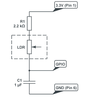
By using a simple circuit you can measure multiple level of values using a single GPIO pin. It consists of a basic “RC” charging circuit in which a Resistor in placed series with a Capacitor. Voltage across the capacitor rises when voltage is applied across the RC network. Using the formula [t = RC ] where t is the time, R is resistance in ohms,and C is capacitance in Farads and the time taken to register a HIGH on a GPIO pin we can roughly estimate the analog value. Here are the list of steps to read analog values from digital pins.
- Set any GPIO pin as an output and set it Low.This ensures that no charge is present in capacitor and both the terminals are at 0V.
- Now set the GPIO pin as an input.This will starts a flow of current through the resistors and through the capacitor to ground. The voltage across the capacitor starts to rise. The time taken will be proportional to the input.
- Read the value from GPIO pin and keep incrementing a counter variable until the value is LOW.
- At some point the value from GPIO will register a HIGH. When it does return the value of the counter.
- Set the GPIO pin as an output and repeat the process as required.
Example Circuit:-
Now you know how to get and use analog data on your digital device. With the power of the Raspberry Pi, you don’t have to stop here. You can archive temperature data by storing the values in a MySQL database (using the Python MySQL connector), send them to an email address (using the Python SMTP methods), and so on.
No comments:
Post a Comment